Table Of Content
Another important reason for using IIR filters is their small group delay relative to FIR filters, which results in a shorter transient response. With the DSP System Toolbox you can quantize from double-precision to single-precision. If you have the Fixed-Point Designer, you can quantize filters to fixed-point precision. Note that you cannot mix floating-point and fixed-point arithmetic in your filter. When you choose to export to the MATLAB workspace or to a MAT-file, you can export the filter as coefficients. If a DSP System Toolbox™ is available you can also export your filter as a System object.
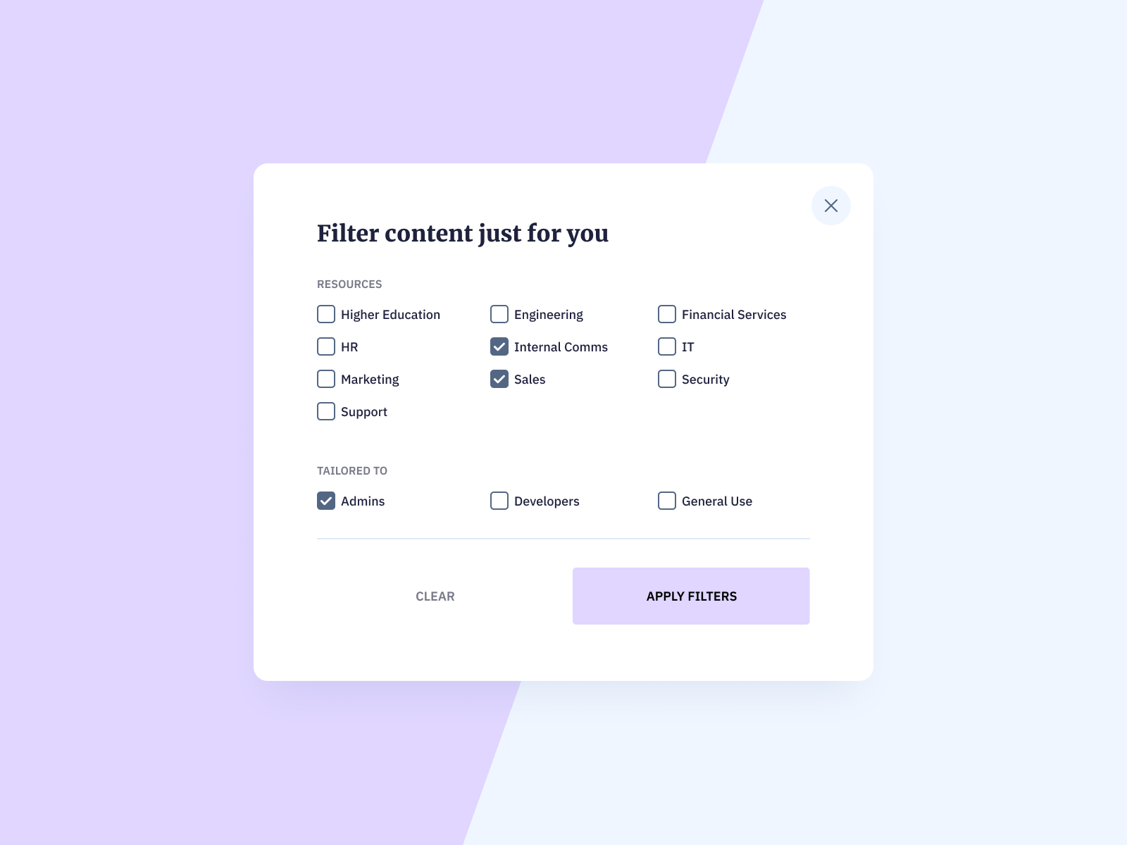
Avoid Layout Shifts On Filter Input
With minimum-order designs, the ideal order needs to be rounded to the next integer. This additional fractional order allows the algorithm to actually exceed the specifications. If you know the sample rate at which the filter will operate, you can specify the sample rate and the frequencies in hertz. Design a filter with the same specifications as above using the Kaiser window method and compare its response to the equiripple filter. The triangle is used to understand the degrees of freedom available when choosing design specifications.

Custom filters from anywhere

Rather than using a set of input fields, Made.com chose to use a visual interface with a “Resize” icon. You can drag the handle to adjust the size, or you can type in exact values in the height and width input fields. After just a few usability sessions with customers who try to use filters on their own device, one can spot some common frustrations making rounds over and over again. One of the most annoying patterns comes from lengthy filter sections that contain dozens of options. These options often get tucked away in a tiny scrollable pane, showing 3–4 options at a time and requiring vertical scrolling to browse the options. The cue to where it lies can be inferred from how different the options actually are.
Bessel filters
This section sketches an outline of the theory of elliptic- function filter design. The details and properties of the elliptic functions themselves should simply be accepted, and attention put on understanding the overall picture. In conclusion, using the distances from the unit circle to the poles and zeros, we can plot the frequency response of the system. As \(w\) goes from \(0\) to \(2 \pi\), the following two properties, taken from the above equations, specify how one should draw \(|H(w)|\).
Techniques such as surface mount technology (SMT) or printed circuit board (PCB) manufacturing can offer cost-effective and scalable solutions. It is also important to consider the manufacturing tolerances and the impact they may have on the filter’s performance. Learn how to design these specialized filters to suppress unwanted frequencies, nullify interferences, and ensure clean signal transmission in the presence of disruptive signals. Passive filters are composed of passive components such as resistors, capacitors, and inductors.
Optical Filters: Application and Design Considerations Webinars - Photonics.com
Optical Filters: Application and Design Considerations Webinars.
Posted: Wed, 13 Mar 2024 17:24:42 GMT [source]
Methodology
There are really not that many options where they could live though, and a better option seems to be the area above filtering results. We mentioned already that filters and matching results are often somewhat synchronous. However, we could split the parts of the UI and render both of them separately, asynchronously. In that case, on every filter input, matching results could be updated asynchronously, while the filters always remain accessible and at the same place. With every new filter input, the user would see a flash of new content streaming in.
Filter Implementation: Analog or Digital?
Analog (Continuous-Time) filters are useful for a wide variety of applications, and are especially useful in that they are very simple to build using standard, passive R,L,C components. Having a grounding in basic filter design theory can assist one in solving a wide variety of signal processing problems. In certain applications we have to deal with signals which contain components which can be described as local phenomena, for example pulses or steps, which have certain time duration. A consequence of applying a filter to a signal is, in intuitive terms, that the duration of the local phenomena is extended by the width of the filter. This implies that it is sometimes important to keep the width of the filter's impulse response function as short as possible.
Filter topologies refer to the arrangement and configuration of components within a filter circuit. There are several common filter topologies, such as Butterworth, Chebyshev, and Elliptic filters. Each topology has its advantages and trade-offs in terms of passband ripple, stopband attenuation, and rolloff characteristics. Designers must select the appropriate topology based on the desired filter performance.
Discover the Allure of Designer Choker Necklaces: The Perfect Blend of Elegance and Edge
You can smooth a signal, remove outliers, or use interactive tools such as the Filter Designer tool to design and analyze various FIR and IIR filters. You can also compare filters using the Filter Visualization Tool and design and analyze analog filters using built-in functions. The simulation of the lumped element model shows that the lowpass filter has a cutoff frequency of about 2 GHz and has a gentle roll off, which is expected for a Butterworth filter.
To minimize the cost of implementation of the filter, we will try to reduce the number of coefficients by using Minimum Order option in the design panel. In the Display region, you can click on any point in the plot to add a data marker, which displays the values at that point. Right-clicking on the data marker displays a menu where you can move, delete or adjust the appearance of the data markers. Growing out bangs can be a long process, depending on how fast your hair grows. While it's definitely fun to change things up and go for the unexpected, there's something to be said for a classic, flattering cut. Think of it as your home base—the style you can return to time and time again.
Chebyshev Type I filters attain smaller transition widths than Butterworth filters of the same order by allowing for passband ripple. You can design filters with fixed filter order and cutoff frequency using a window design method. A useful metaphor for the design specifications in filter design is to think of each specification as one of the angles in the triangle shown in the figure below. MATLAB® and DSP System Toolbox™ provide extensive resources for filter design, analysis, and implementation.
Depending on the application and the cost, the approximations can be chosen. The optimum filter is the Chebyshev filter with respect to response and the bill of materials. Filters can be designed both in the lumped and distributed form using the above approximations. Analog filter implementation involves using analog components to create the desired filter characteristics.


No comments:
Post a Comment